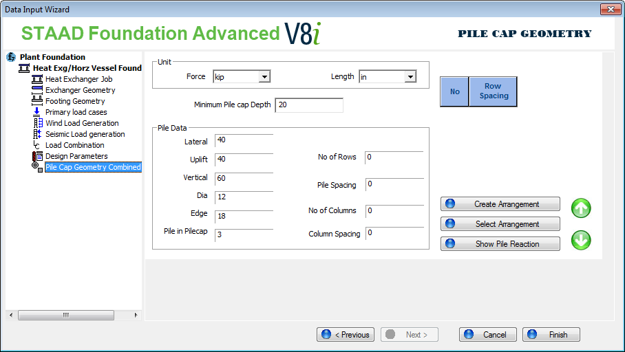
| Unit |
Choose Units for force and length, these units are only applicable to Pile Cap Geometry Page. |
| Minimum Pile cap Depth |
|
| Pile Data group |
| Setting | Description |
|---|
|
Lateral
|
Specify the lateral capacity of a pile.
|
|
Uplift
|
Specify the uplifting capacity of a pile.
|
|
Vertical
|
Specify the vertical capacity of a pile.
|
|
Dia
|
Diameter of a pile.
|
|
Edge
|
The Edge Distance field allows you to specify the distance between the edges of a pile.
|
| Pile in Pilecap |
The pile embedment length into the pile cap.
|
| No of Rows |
Number of piles in the longitudinal direction. |
| Pile Spacing |
Center to center spacing between pile rows. |
| No of Columns |
Number of piles in the transverse direction. |
| Column Spacing |
Center to center spacing between pile columns. |
|
|
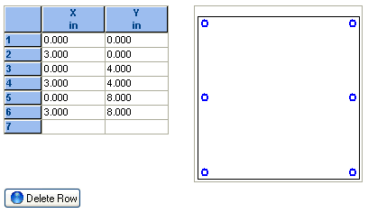
Create Pile Arrangement
|
Creates the pile layout and opens a dialog box to display the pile coordinates table and a figure.
Note: Pile coordinates in this table are editable.
Delete Row - Click to delete the current row from the pile coordinate table and figure.
|
|
Select Current Arrangement
|
Once a satisfactory pile layout has been found, click the Select Current Arrangement button to select and apply that layout.
The program will check the pile reaction against pile capacity to make sure pile reactions do not exceed pile capacity values.
|
|
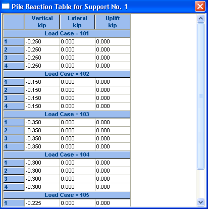
Show Pile Reactions
|
The Show Pile Reactions button opens a table displaying the reaction on each pile. The figure below shows the pile reaction table.
|
| spacing type and table |
Once a pile arrangement is started, the table displays the spacing for each row and column, depending on what table spacing type is selected. |